Wednesday, December 2, 2015

CSWA: To Shell or Not To Shell - Attempt #2

I attempted to explain when a shell would not work in some instances last time.  I need to say thanks to Todd Turner (follow him on twitter at @ttturner68) for starting a discussion with me and giving me an education on the shell feature.  He by far knew more about the feature than I did and I learned a lot from him.  I've archived that post and am attempting to explain the concept a different way.

Let me start off attempt #2 with setting the stage a bit.  Let's specify that this post is intended for the new user, with a few months of experience using SOLIDWORKS.  You can do the below example with a shell feature, but it would take some more advanced features that are not included in the 'what you need to know section' of the CSWA exam.  I want to also add that on most of the certification exams, you are led down a path by modeling a part, then modifying it several times.  This can put you in a place where if you were told to model a part from scratch, you would do it one way, but given the part as the 2nd modification, there just isn't time to start over, especially if there is another modification coming at you on the next question.

With that said, let's look at an example that offers us some more challenges.

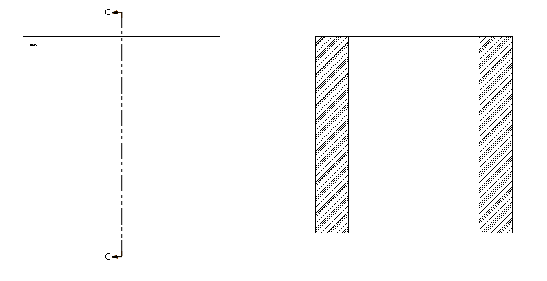
We are given this part.  It has a rounded top with a square post.  On the inside of the rounded part, it has a cam type feature.  Let's say we need to remove some mass from the top of one of the lobes of the rounded top, so we are asked to create a cut out.  This is a situation where we might think about shelling it out.  Especially if the next question were to ask us change the thickness of the wall.


If we use a shell in this instance, the shell will attempt to shell down the post, around the lobe and up the other side of the rounded top.  This is not what we want to attempt.  In the case above, barring the use of some more advanced techniques, I would advise a simple cut extrude.

If you have any questions, please leave them in the comments below.

Thanks,

Bryan

Monday, November 9, 2015

CSWA: Global Variables

SOLIDWORKS loves to use variables and equations on their exams.  Getting used to them is of the utmost importance in order to quickly change information in your models.  This allows them more options in testing answers as they can change the variable dimensions given in the written instructions at will and in any combination.

If you read through my post from the CSWP exam on Equations, you will see much the same information is covered.  The CSWA is a little easier.

Before starting your exam, I recommend turning on Equations and Sensors.  This gives you the option to add each from the design tree and you don't have to go hunting through menus to find them.

Run through this exercise to practice adding Global Variables and Equations.  Global Variables and Equations

Make sure you are comfortable with changing the variables and always remember to rebuild your models.

Bryan

Friday, October 30, 2015

CSWA: Types of Views

A big part to properly using SOLIDWORKS is knowing what views should be used in certain situations.

You will find several questions on the CSWA exam that asks you to identify what type of view is being created.  I've whipped up a few types below.

Look them over and see if you can identify them.  I've put the answers at the bottom.  Make sure you are familiar with all view types before starting the exam.

A)
 B)
 C)
 D)
 E)


A) Broken Out
B) Break (Vertical)
C) Crop
D) Detail
E) Section

Wednesday, October 28, 2015

Introduction to the CSWA

The Certified SOLIDWORKS Associate exam is geared as the entry level exam to test your SOLIDWORKS knowledge.  SOLIDWORKS recommends you have about 3 months of usage under your belt, have gone through all the tutorials and have taken the Essentials class.

There is a link to a sample exam located here.  Click on the Sample CSWA Exam link to access it.

The test is limited to 3 hours in length and you have to score a 70% in order to pass.  If you happen to need to retake the exam, you will have to wait 30 days between testings.

You will cover topics such as:

  • Sketch entities - lines, rectangles, circles, arcs, ellipses, centerlines
  • Sketch tools - offset, convert, trim
  • Sketch relations
  • Boss and cut features - extrudes, revolves, sweeps, lofts
  • Fillets and chamfers
  • Linear, circular, and fill patterns
  • Dimensions
  • Feature conditions – start and end
  • Mass properties
  • Materials
  • Inserting components
  • Standard mates - coincident, parallel, perpendicular, tangent, concentric, distance, angle
  • Reference geometry – planes, axis, mate references
  • Drawing views
  • Annotations

Marie Planchard, Director of Education Community recently told me that over 70% of CSWA exams are coming from colleges.  They have further developed a special CSWA-Academic Certification that carries a bit more industry clout.  

Michael Puckett, Senior Manager, World Wide Certification Program SOLIDWORKS, goes on to say that while both exams are the same, the CSWA-Academic exam is only given under a proctored environment and is only offered by academic institutions that are part of the CSWP Provider Program.  

Both  Marie and Michael confirm that the test is given under rigid guidelines and the provider must meet certain requirements in order to be able to offer the CSWA-Academic.  The test taker that passes the CSWA-Academic is given a special certificate with the testing institutions name on it.

As the college semester in the US is starting to wind down, I want to try and cover a lot of tips and tricks that can help everyone pass the CSWA, either the standard or academic.

Let me know if you have any questions by posting a reply.  Otherwise, I'll try and burn through this exam and explain some of the concepts.

Thanks,

Bryan

Tuesday, September 8, 2015

Next Discussion: CSWA

We will start our next topic, the CSWA, in a couple of weeks.

I'm going to take some time off in order to attend an event in Boston to see what SOLIDWORKS 2016 is going to look like.

I'll be tweeting and blogging on the new version of our favorite software from the certification point of view.

If you have any questions, post them here or hit me up at my twitter account SWCertGuy.

Enjoy!

Bryan

CSWP, Segment 3: Replace Component

SOLIDWORKS also makes it very easy to replace one component with another.  Let's work with the assembly we have used in the last couple of posts Here.  Also download the Updated Cross Member found Here.

We are going to right click on the Cross Member and select Replace Components.  You may need to click on the double down arrow if it is not immediately one of your choices.

Cross Member is added to the Replace these components window.  Next we click Browse and browse to the Updated Cross Member file and select it.  One thing we want to select is the Re-attach mates box.  This will compare identical features and re-create your mates for you.

Hit the check mark and you are done.

I hope this helps you out.  Let me know in the comments if you have any questions.

Bryan

Thursday, September 3, 2015

CSWP, Segment 3: Interference Detection

We will take a look at interference detection in this post.  Download the assembly files we used in the flexible assemblies post Here.

Interference Detection is a built in feature in SOLIDWORKS.  Under the Evaluate Tab, you can find it as the yellow and green parts shown colliding.  When we click on it, we open the Interference Detection dialog box.  You can calculate the entire model or select components in your assembly.  If we click calculate with the entire assembly selected, we are shown that the Spacer and Cylinder Housing have an interference condition.


As always, if you have any questions, please ask them in the comments section.

Bryan

Tuesday, August 25, 2015

CSWP, Segment 3: Flexible Assemblies

Lets talk about flexible assemblies on this one.  Here is a dropbox link to the files I'm discussing in this post.  This is the first time I am doing this with an assembly.  If there are any problems downloading, please post in the comments section and I'll try and work it out.

There was a question via twitter on how to put an assembly inside an assembly.  After thinking about it, I think the best answer is that you put an assembly inside an assembly the same way you put components inside an assembly.  The mates are the same, you just get the added benefits of sub assembly mates that you can update at the sub assembly level.  If there are any questions about this, please ask in the comments section and we can discuss it further.

We are going to move onto flexible assemblies and collision detection.  I'll be honest, before the CSWP, I did not know you could make a sub assembly flexible.  Crazy right?  So, it's a simple matter.  If you open up the Segment 3 Assembly file in the folder via the link above you will see a Cylinder Assembly located in the design tree.

If we right click on the Cylinder Assembly in the design tree, we can select Component Properties and open our Component Properties window.  In the bottom right hand of this window, you will see a Solve as area.  Change it from Solid to Flexible.  Going back through this, I also noticed that SOLIDWORKS loaded this as lightweight in my session.  It will need to be resolved before you can select flexible. Doing this will allow the sub assembly to use the mates in the sub assembly to solve for location of the piston inside the cylinder.

Now if we look again at our main assembly, you can see that we can grab one of the cross members and move it around and it will actuate the cylinder.  Granted, you could do the same thing if you put the components into the main assembly individually, but what if you purchased this cylinder and the supplier gave you an assembly model?

Next, let's look at collision detection.  Say we want to know how far the cross members will actuate when the cylinder is fully retracted.  Select the Move Component function from the Assembly tab, in the Move Component window, select Collision Detection, These components, then click on the piston and cylinder.  Click Resume Drag and then grab the cross member in the model and drag it.  You'll notice when the cylinder is fully extended, the cross members just sweep by each other and flip to the bottom of the assembly, but when you drag it up, it stops.  If you have the transparency turned down on the piston and cylinder, you can see that the piston bottoms out in the cylinder and the assembly stops.  If we leave it at the stopping point, what is the angle between the two cross members?


Next time we will look at interference detection.  As always, if you have any questions, please ask in the comments section.

Enjoy,

Bryan

Tuesday, August 18, 2015

CSWP Segment 3: Origins and Coordinate Systems

Segment 3 is about assemblies.  It becomes nearly impossible to judge if your assembly is correct based on mass.  Therefor we switch to reporting the Center of Mass or Center of Gravity.  Because of this, we have to pay very close attention to the polarity of our answers.  A negative sign can mean the difference between right and wrong here...

For example, the question in the box below can be answered without opening SOLIDWORKS.


You can see that Z and Y must be positive and X must be negative.  If Z is positive, then this eliminates the top two answers.  If X must be negative, this eliminates the bottom left answer, leaving us with only one option, the bottom right.

So, it is important that you create and assemble your models with the origin in mind.  If for some reason, you find yourself 3 questions deep and realize your coordinate system is wrong, there is a simple fix.  We can use a Reference Coordinate System.  Click Insert, Reference Geometry, Coordinate system to open the feature.


Select Edges to make the Reference Coordinate System match the test.


Hit the check box and you have a secondary Reference System.  When computing the Center of Mass, make sure you have the new coordinate system selected in the window shown here.


On the next post, we will talk about how to insert a sub assembly and make it flexible.

Have Fun,

Bryan

Wednesday, August 12, 2015

Questions

I'm getting some questions through twitter about specific items.  If you have a question, please reply to this post and I'll do my best to answer them.

Bryan

Monday, August 10, 2015

CSWP Segment 2: Design Intent

I'm going to finish off Segment 2 on this post.  Let's download and open this file: Shelled Part - Design Intent.  It is a model of a wrench for a hex nut.  I believe this section of the test explores your ability to understand design intent.  There are several questions in this section of the test where you will have to understand how a model is created and to find the best way to update it based on the design intent.


We start off with a question that asks you to change the wall thickness of this part.  I want to touch on this briefly.   I have a lot of questions in my classes about shells.  In the CSWA exam, there is a question that leads the test taker down this path only to be faced with some serious issues when using it.

If we want to update the wall thickness, we would need to edit the shell feature and change the value from .125 to .250.  As easy as that sounds,

Once the wall thickness is updated, determine the mass of the part.


Now, to focus in on the design intent portion.  If we take the part we downloaded above, we can see the part and sketch that we start off with looks something like this:


Let's take the above and make a change to the base feature profile so that it looks like this:

You can see that once we rebuild, the part looks like something that we would consider a good part, meaning that there is nothing that indicates a problem.

Let's revert back to the original downloaded state and extrude a cut on the front surface through the entire model.


When we rebuild the part, we see that we have a problem...  That cut extrude broke out on the bottom of the handle.


The reason is directly related to the design intent or the way the model was built.  We have a base shape, then we immediately move into a shell feature.  Now if we cut extrude this feature through all, we see that the shell does not perform like it should.  This is due to the shell command offsets from the outer surfaces to create the shell feature.  We do in fact want the handle to be tapered on 3 sides, but we do not want the shell to break out of underside of the handle.  

There is a very simple fix to this to follow the original design intent.  As you can see in our design tree, our sketch and cut extrude are at the bottom of the tree.  So we built our base feature, then shelled out based on that shape.


The correction is to drag the new feature to a location above the shell.  When we do that, we can see that the shell now follows the new surface in addition to the previous surfaces.


I hope this helps everyone on Segment 2.  I've got some special requests for Segment 3.  I'll be posting some stuff on that soon.

Enjoy!!

Bryan

Tuesday, August 4, 2015

CSWP Segment 2: Design Tables

Design tables can sometimes be confusing.  I've seen very simple design tables and I once saw someone use a design table and Excel's Goal Seek function to determine the level of water in a tank of a specific weight and update the model to the correct volume of water.  As it relates to the CSWP exam, we need to learn how to create a table and use it to control some basic dimensions.

Once again, let's start with downloading the 2014 Version File that we have used on the last to blog entries.  With the model opened, we can click Insert, Tables, Design Tables (see left) and open the dialog box shown to the right.

We are going to select the Auto-create button under Source.  This will read our model and find any differences and populate them in the design table.  Edit Control dictates whether your model will control your design table or if your design table will control you model.  This can be set based on your needs.  We will use the first option.  The options section tells SOLIDWORKS what to consider a Design Table entry.  We will select the first two.  Once we have all our selections made, we click the check mark.  Your interface will bounce around a bit and you will be presented with an Excel sheet in your Graphics User Interface that contains all the current configurations and it will also review the model and list all dimensions or states that are different.  You can see below that the model is populated with the 5 configurations that we have used in the last two posts, it has populated the various lengths of the file and we see there are a sketch and a feature that have different suppression states.


The design table operates using Excel.  Any formulas of features you use in Excel are usable here.  We need to make a new configuration, so, let's copy the entire row labeled in Column A as 10" and paste it into the next empty row.  If you leave a blank row or column, SOLIDWORKS will recognize this and consider it the end of your design, so make sure there are no blank rows or columns.


We don't need two configurations named 10", so let's rename Column A and B to 16".  We will then go into Column D and change the value to 16.  This represents how long the cylinder is.


In order to exit the Design Table, you just need to click outside the design table in the GUI.  Trust me, when working with Design Tables, you will do this on accident multiple times.  :-P  (see below on how to get back into the Design Table)

It will do some more bouncing and throw you a dialog box similar to this:


When you select OK, your configurations manager will give you a new symbol next to your configurations.  It is the symbol for Excel which indicates that the configuration is controlled by the design table.  To edit the configuration, you have to enter the design table.  In order to do this, you need to click the plus sign on the Tables folder, right click the design table and select edit table.


Quick Check and the question everyone is asking...  What's the mass?


Outside the Exam, Design Tables are a very powerful feature.  We use them in my daytime job to control our customer models.  The customer fills in some drop down boxes on our website, this gets shoved into the design table and out pops the model the customer needs.

Enjoy,

Bryan

CSWP Segment 1: Adding Material and Checking Mass

In Segment 1, it's all about mass.  Every question asks you what the mass of the part is.  In order to get the mass, we need to tell SOLIDWORKS what material we are working with.

Let's back up to the model we created when we were talking about equations.  Let's set A=30, B=10 and C will evaluate to 50.

The first thing we need to do is assign a material to the part.

Right click your part in the Design Tree
Select Material, then Edit Material


Select the material you have been asked to use from the list (1061 alloy in this case).
Click Apply, then Close.


Now, let's add a sensor.

Right click on the sensors folder and select Add Sensor


Under the Properties tab, select Mass and click the check box.


Expand the Sensors folder and you will see what the mass of the part is.


The sensor will update as you modify your part.  I recommend using it as a general input to if you are going in the right direction.  When it comes time to enter your answer, I highly recommend that you double click on the mass in order to open the Mass Properties window.  You can set this to the number of decimals that the test requires answers to be given in.  This eliminates one more chance for a mistake by rounding numbers in your head...


I hope this helps on segment 1.  If you have any questions to anything I've posted on segment 1, please post them below.

Next time, we'll take a look at Segment 2.

Bryan

Monday, August 3, 2015

CSWP Segment 2: Adding Configurations

I'm going to break creating configurations up into two sections.

The first method is the simplest, but offers the least amount of options on the front side.  In essence, you can only add a configuration and then name it.  After you have done this, then you can modify it.  Let's take a look at this method.

Let's use the same model from my last entry.  Open 2014 Version File of the Cylinder.  Open the configuration manager, right click on the parent part and select Add Configuration.

In the pop up window that we are given, enter 12" with lug hole in the configuration name and click the check mark.  It's as easy as that.  Now that you have a configuration, let's look at what we can do with it.


We have our new configuration and it is active, so let's make it distinguishable from the other configurations.  We are going to add a lug hole to the cylinder.  Sketch a .2500 diameter hole on the mounting lug as shown here and extrude cut it through all.


Let's take a look at the configure feature function.  Right click on the cut extrude feature we just created and select 'Configure Feature'


Let's suppress this new feature in the 10", 12" and 14" configurations.


Now, if we switch to the 8" configuration, we see our lug hole, but if we switch to the 14", the lug hole is not turned on.  And the question you most love to see, is what is the mass of the 8" configuration?


The next entry will be doing the same thing with a Design Table.  It gives a little more flexibility on the front side than the 'Add Configuration' method above.

Bryan

Friday, July 24, 2015

CSWP Segment 2 - Configurations

This entry we are going to discuss configurations.  Some people deal with configurations all the time, while others have never dealt with them.  Segment 2 deals heavily with controlling configurations.  We will look at two items that might be of interest on an exam.


First, let's start with downloading and opening a SOLIDWORKS file.  It is a 2014 Version so you will be able to open it in 2014, 2015 or beta 2016.


The first thing you are going to want to know is how many configurations there are.


Let's switch to the configurations tree by clicking the configurations tab and counting how many different configurations there are.

As you can see, there are 4 configurations.  The configuration that is active is the 8" configuration.  You can tell this because it is not grayed out.

Let's switch to the 12" configuration by double clicking on it.


You can now see that the 12" is now colored and the 8" has been grayed out.  The check mark signifies that the configuration has been through a 'resolved or rebuild' function.


The last question for this post is, what is the mass of the 12" configuration?


0.1570 pounds is the answer.

Next time, we will continue on with adding configurations using 'add configuration' and a design table.

Bryan

Tuesday, June 30, 2015

Reading Chamfers

I've got a short post today.  We need to talk about chamfers and how the test shows them.  We all know that there are multiple ways to dimension a chamfer on a drawing.  The exam uses a couple of different ways.

Here are a few ways you will see chamfers on the exam.


The key to chamfers on the exam is to know where the reference plane is.  If you are shown a 45° chamfer, the orientation does not matter, but when you are given a 60°, the reference surface becomes very important.  Here is an example for defining an edge chamfer.


Also, one word of caution, I've had several instances, more in the past, where chamfers flip on you in patterns or mirrors.  Be wary of the chamfer...

Until next time,

Bryan